
The Problem
Multiple SCARA arms needed to print on the same build surface without gaps or layer shifts where their paths met. Small errors in link lengths, joint references, or base position displaced each print head. The calibration target was 200 µm (0.2 mm) positioning accuracy.

The Engineering
I built a Python calibration solver around paired target and measured X–Y positions. It uses the nominal arm geometry to infer joint offsets at each reference point, then fits six physical parameters: two link lengths, two angle references, and the base X–Y position. The solver repeatedly predicts each point’s position and reduces its error against the target, producing corrected parameters for the motion model.
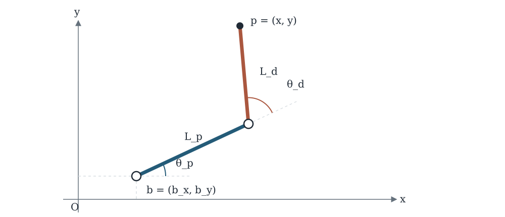
The example input pairs each target X–Y position with an arm measurement and the nominal geometry. Inverse kinematics estimates the joint angles at each measured point, and the solver keeps those offsets fixed. Forward kinematics then predicts the target positions while bounded updates fit the two link lengths, two angle references, and base X–Y position to reduce squared position error.
The fitted parameters can replace the nominal geometry in the arm’s motion model. The animation below exposes those same variables, showing how each one changes the predicted print-head path and the square it draws.
Interactive forward kinematics
Watch the arm draw a square
A forward-model simulation of the square, not a robot recording. Change a parameter to see its effect.
Model parameters
01 · Base position
Move the whole arm02 · Proximal link
Base to elbow03 · Distal link
Elbow to print headProximal length: Extends or retracts the blue link from the base to the elbow.
The Results
Calibration improved positioning accuracy 50× and met the 200 µm target. In the grid traces below, the uncorrected arm bends lines that should be straight and shifts their intersections. With the calibrated parameters, the pattern is straighter and more consistently aligned. This accuracy allowed multiple robots to work on the same printed object without visible seams or layer shifts where their paths meet.
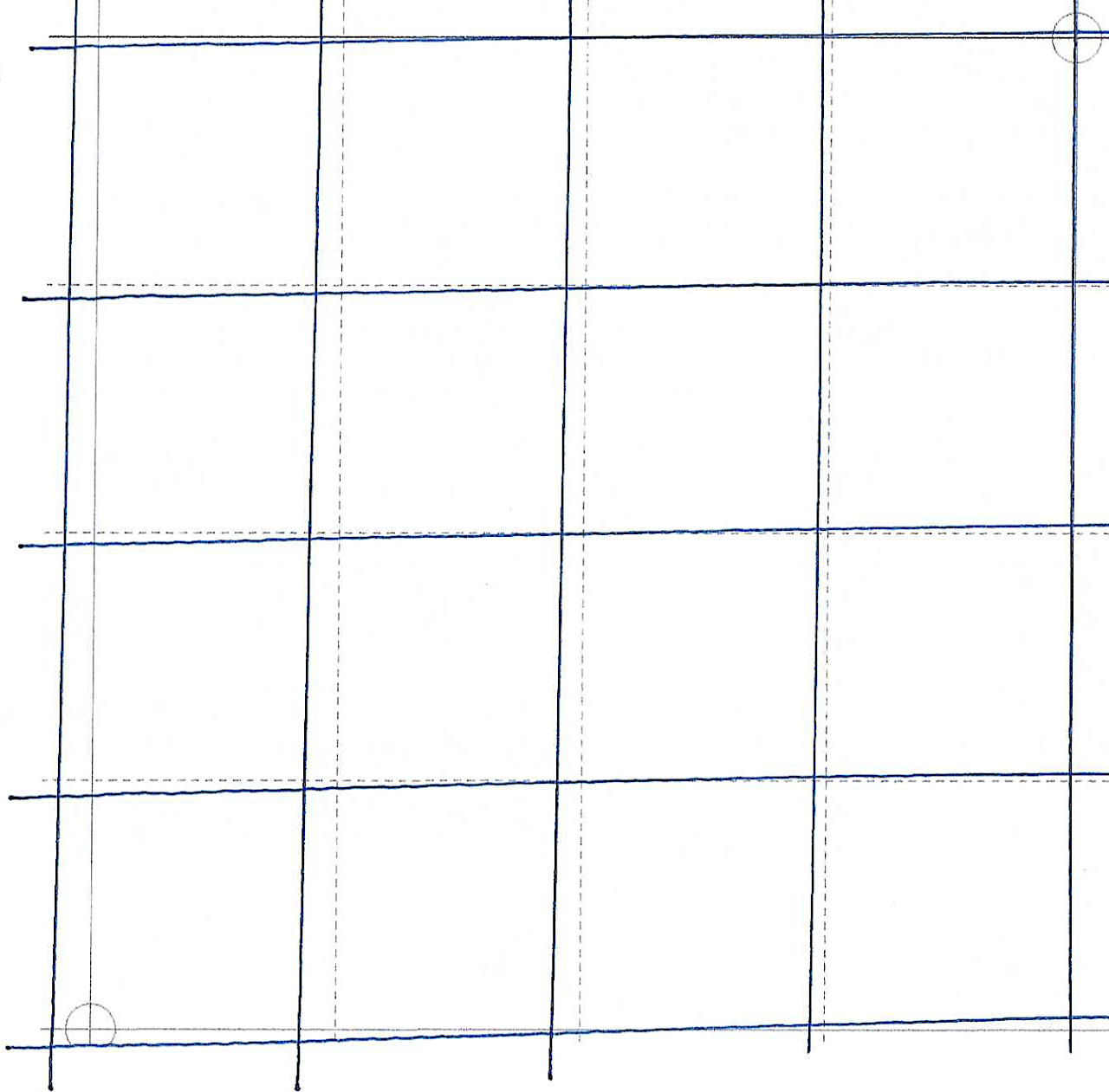
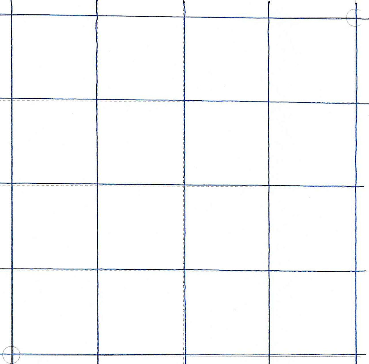
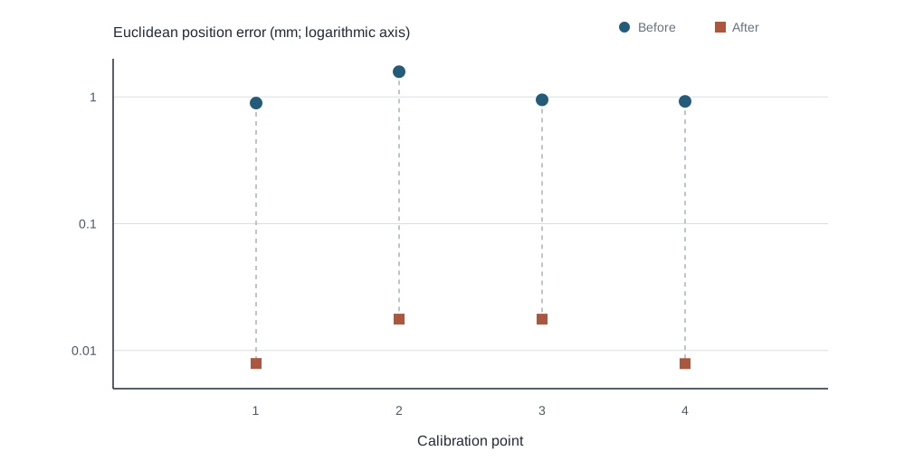
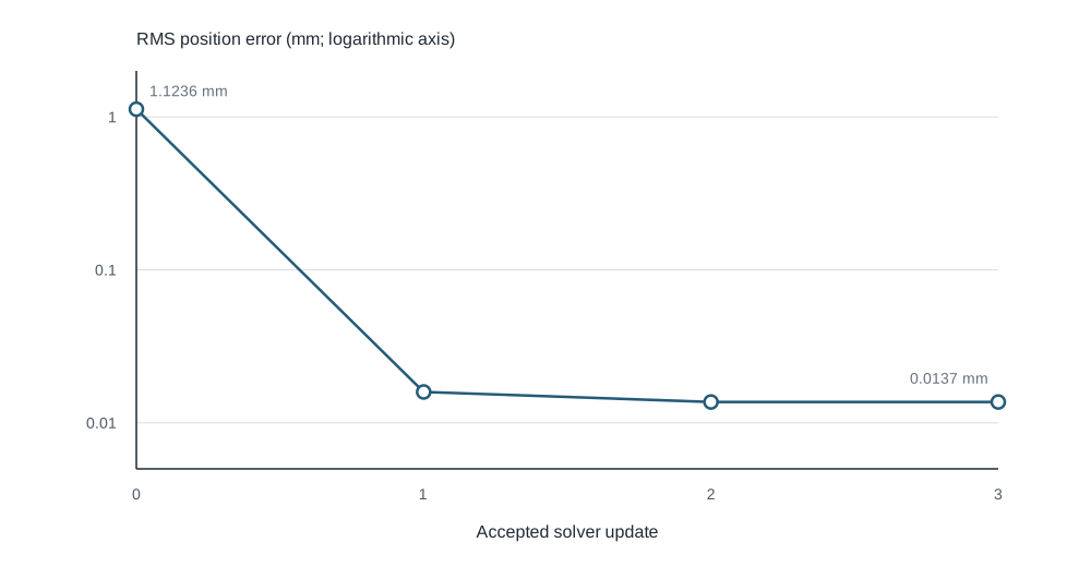
The plots below show what the solver did during a four-point sample run. The position-error chart compares the error at each reference point before and after fitting, while the convergence chart follows the RMS error through accepted updates. Together, they show how adjusting the arm geometry brought the predicted positions closer to their targets.